Difference between revisions of "Laser Confined Nuclear Fusion"
| Line 21: | Line 21: | ||
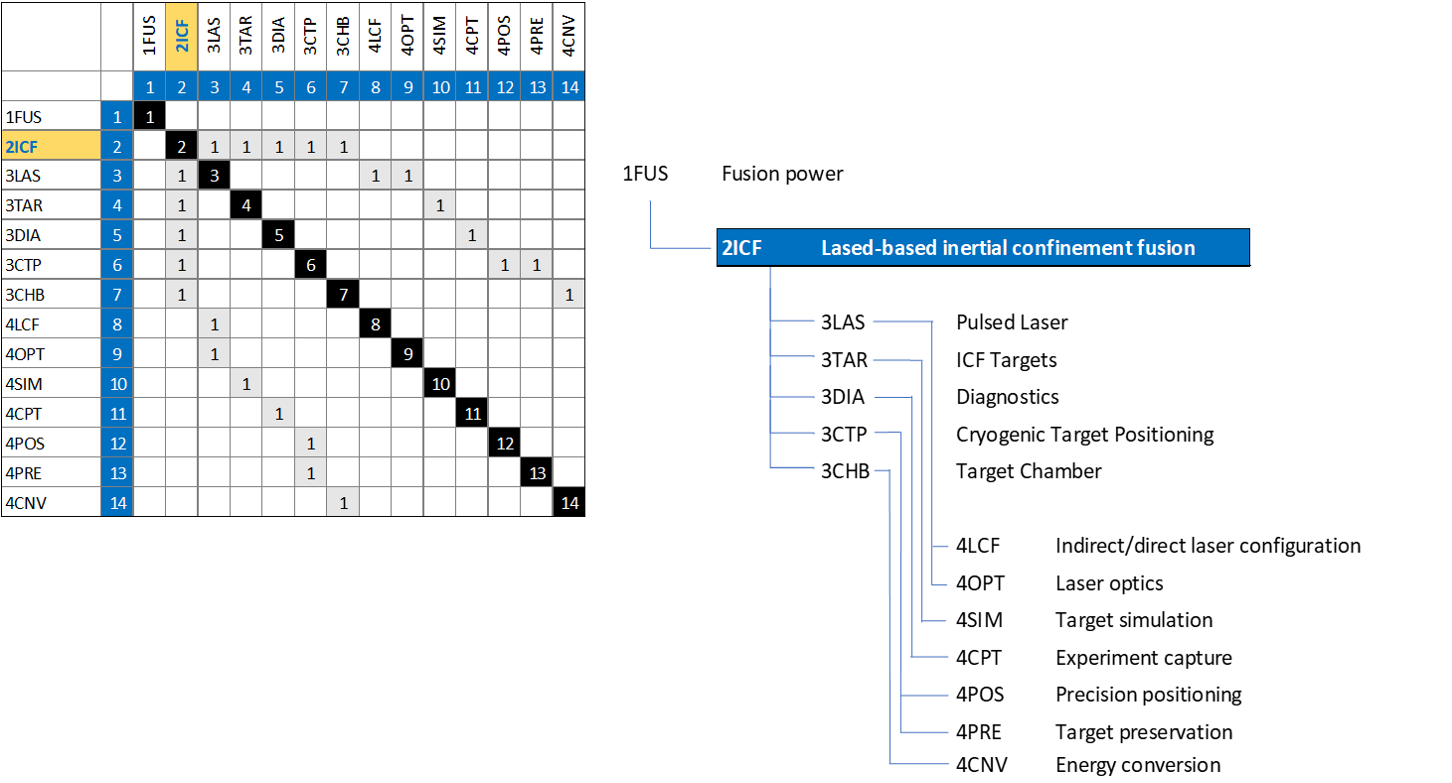
The 2- | The 2-ICF tree shows us that Laser Confined Nuclear Fusion is part of larger global Nuclear Fusion Power initiative to harness fusion power. The DSM and tree both show that 2-ICF requires the following technologies at the subsystem level 3: 3LAS Laser, 3TAR ICF Targets, 3DIA Diagnostics, 3CTP Cryogenic Target Positioning, and 3CHB Target Chamber. Each level 3 subsystem also require enabling technologies shown as level 4 systems. | ||
==Roadmap Model using OPM== | ==Roadmap Model using OPM== | ||
Revision as of 12:27, 1 October 2020
Note: This sample technology roadmap is taken from the example provided in Chapter 8 of the book. For the full discussion, see the Chapter. This page is meant only as an example of how the sections of your team's technology roadmap should be organized and formatted on this XLP.
Technology Roadmap Sections and Deliverables
- 2ICF - Laser Confined Nuclear Fusion
Roadmap Overview
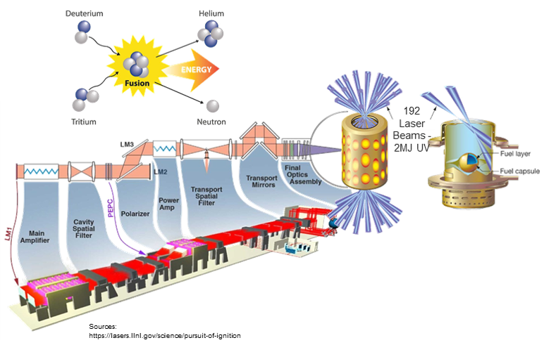
The working principle and architecture of Laser Confined Nuclear Fusion is shown in the schematic below.
Nuclear fusion power generation fundamentally consists of fusing atoms to form heavier ones with a release of energy through neutrons. One of the main technology branches for demonstrating fusion power is Inertial Confinement Fusion, ICF which involves rapidly compressing a D-T (Deuterium-Tritium) fueled target pellet using some of the world’s most powerful lasers. The National Ignition Facility, at LLNL employs 192 UV laser beams at ~2MJ to converge on a gold cylinder, the size of a dime to generate x-rays and accelerate the fuel radially inward in less than 1 billionth to produce helium and high energy neutrons that could be captured to create a future energy source.
Design Structure Matrix (DSM) Allocation
The 2-ICF tree shows us that Laser Confined Nuclear Fusion is part of larger global Nuclear Fusion Power initiative to harness fusion power. The DSM and tree both show that 2-ICF requires the following technologies at the subsystem level 3: 3LAS Laser, 3TAR ICF Targets, 3DIA Diagnostics, 3CTP Cryogenic Target Positioning, and 3CHB Target Chamber. Each level 3 subsystem also require enabling technologies shown as level 4 systems.
Roadmap Model using OPM
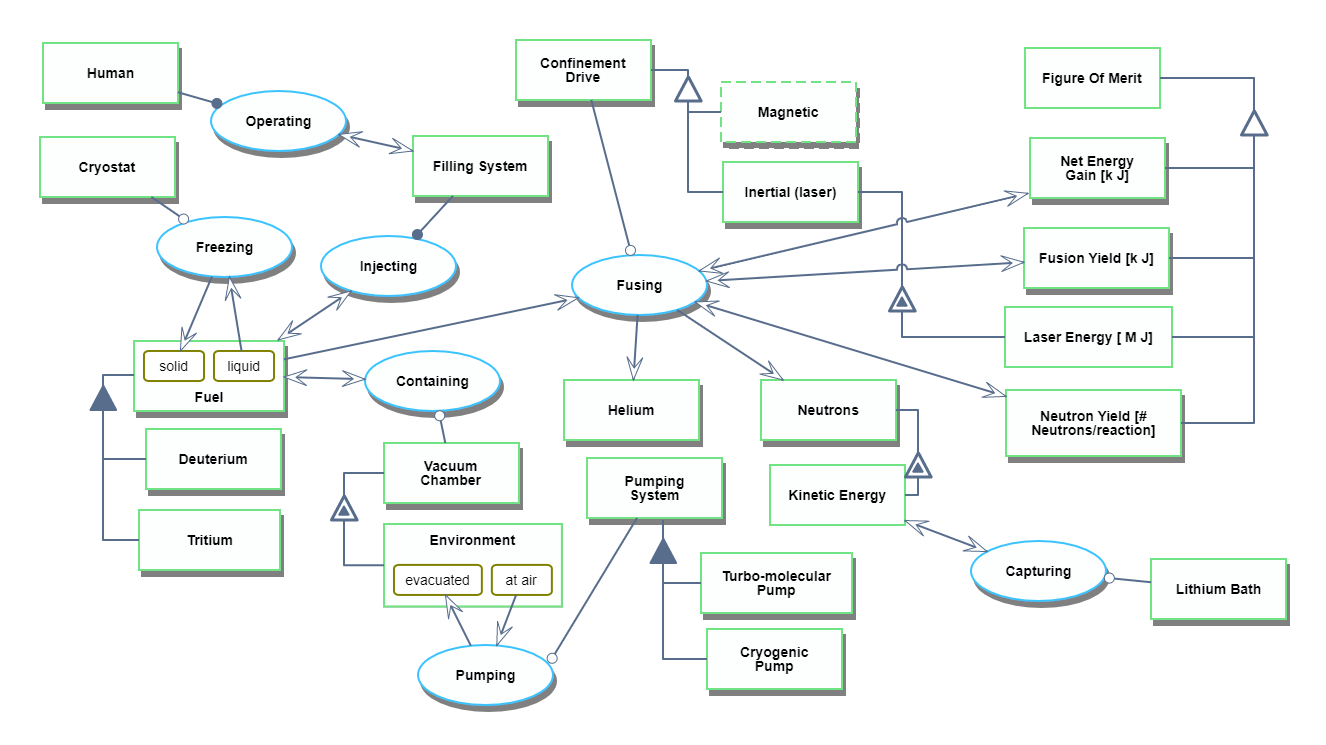
We provide an Object-Process-Diagram (OPD) of the 2SEA roadmap in the figure below. This diagram captures the main object of the roadmap (Solar-Electric Aircraft), its various instances including main competitors, its decomposition into subsystems (wing, battery, e-motor …), its characterization by Figures of Merit (FOMs) as well as the main processes (Flying, Recharging).
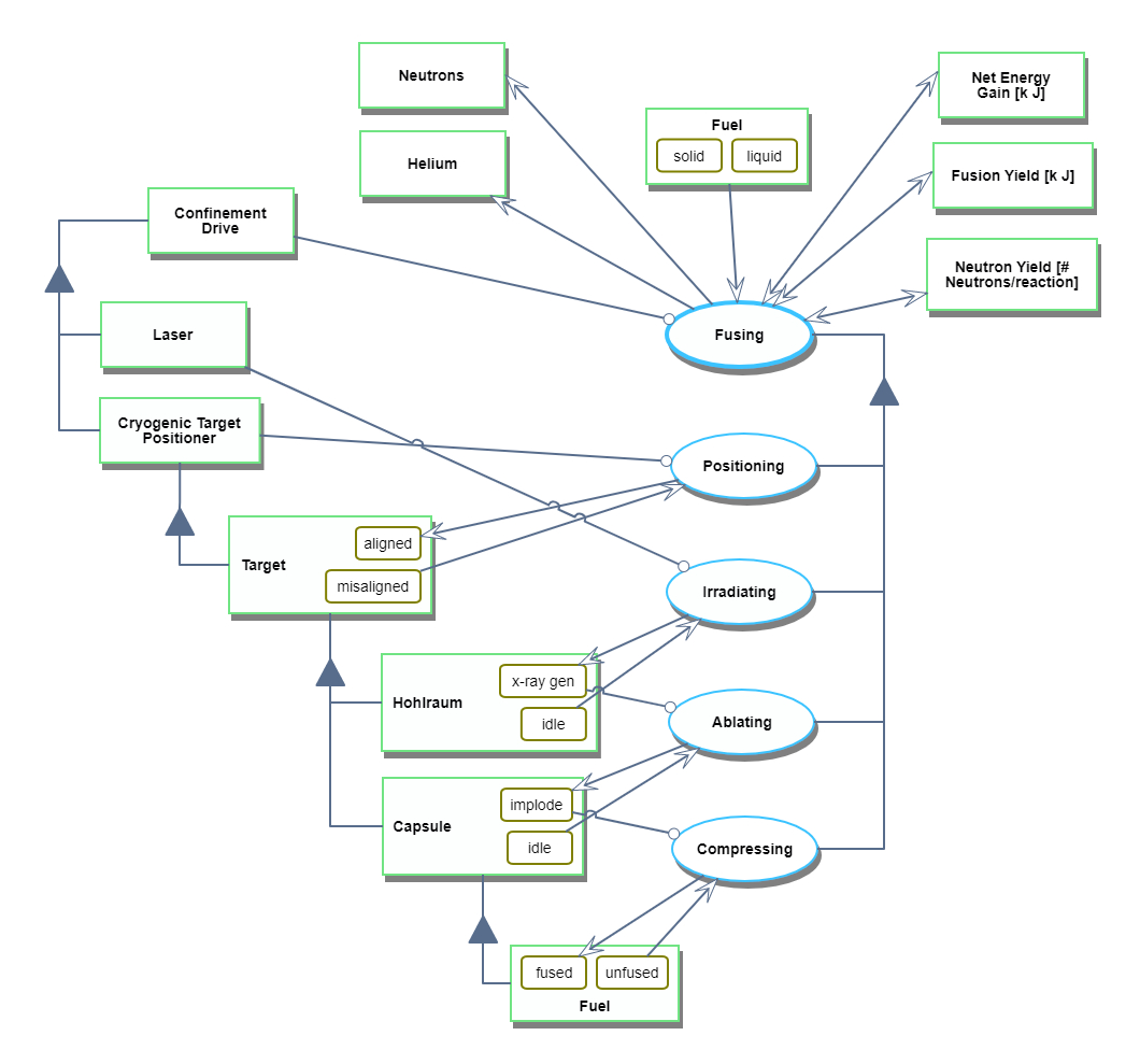
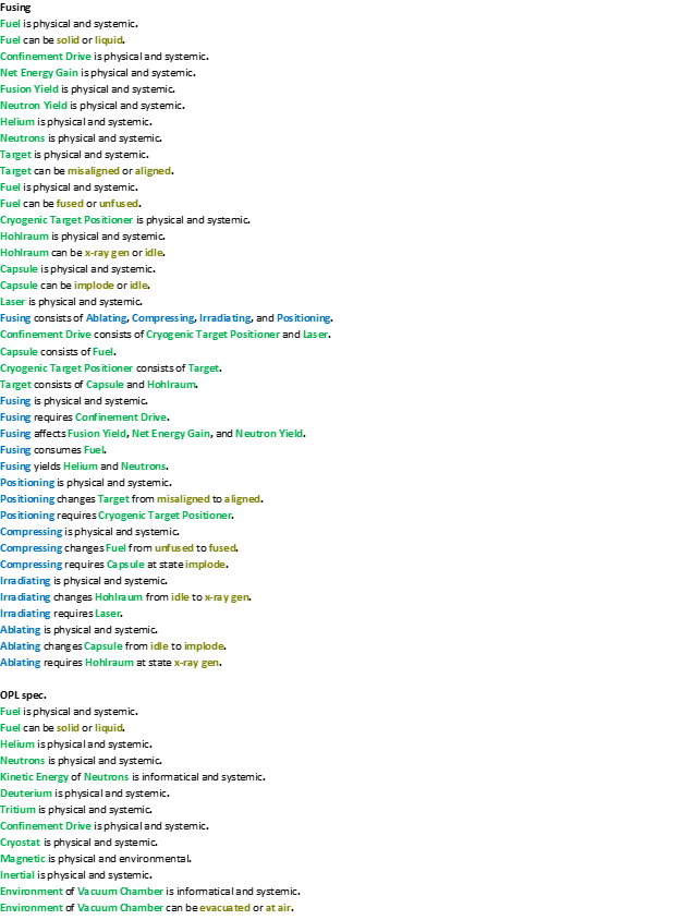
Unfolding the Fusing Process at level SD1
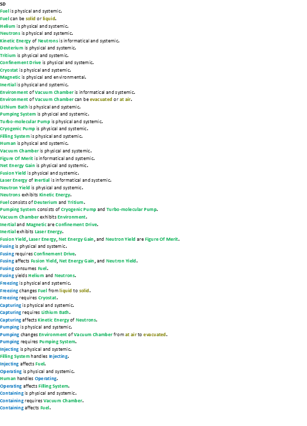
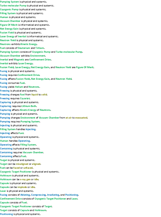
An Object-Process-Language (OPL) description of the roadmap scope is auto-generated and given below. It reflects the same content as the previous figure, but in a formal natural language.
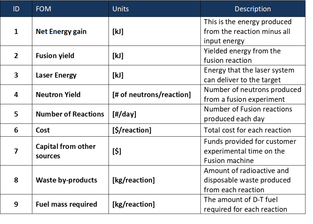
Figures of Merit
The table below show a list of FOMs by which solar electric aircraft can be assessed. The first four (shown in bold) are used to assess the aircraft itself. They are very similar to the FOMs that are used to compare traditional aircraft which are propelled by fossil fuels, the big difference being that 2SEA is essentially emissions free during flight operations. The other rows represent subordinated FOMs which impact the performance and cost of solar electric aircraft but are provided as outputs (primary FOMs) from lower level roadmaps at level 3 or level 4, see the DSM above.
